
No More Mistakes with Flour Mill Machine Manufacturer
Mar 11 2023
Engineering drawings serve as the universal language of manufacturing and design, ensuring that components are produced with precision and consistency. One of the most critical aspects of these drawings is the application of Geometric Dimensioning and Tolerancing (GD&T), specifically the GDT profile symbol. The GDT profile provides a standardized way to control the form, orientation, and sometimes location of complex surfaces and features. Creating a perfect GDT profile is essential for engineers, designers, and manufacturers to communicate design intent effectively and achieve accurate production results.
In this article, we will explore the principles behind creating an effective GDT profile, the steps involved in applying it correctly, and the common practices to follow in engineering drawings. With five detailed sections, you’ll gain insights into the fundamentals, best practices, and techniques to ensure your GD&T usage achieves the intended results.
The GDT profile is one of the most versatile symbols within GD&T because it can control the shape of a surface, its orientation, and its position simultaneously. Unlike linear dimensions or traditional tolerancing methods, the profile symbol defines a tolerance zone around a surface or feature. This zone ensures that the manufactured part lies within a boundary that reflects the designer’s intent.
The profile tolerance can apply to complex 3D surfaces, simple curves, or straight lines, making it widely applicable across industries.
To create a perfect GDT profile, it’s crucial to understand its types: profile of a line and profile of a surface. The profile of a line controls the shape of a line in a specific cross-section, while the profile of a surface controls the entire surface. For example, in aerospace and automotive industries, where aerodynamic or aesthetic shapes are vital, surface profile tolerances play a significant role. Once the designer understands these fundamentals, they can apply the profile symbol in a way that reduces ambiguity, improves manufacturability, and ensures that inspection criteria are clear.
The first step in creating a GDT profile is to identify the critical features of the part that need control. Not every feature requires a profile tolerance—only those that significantly impact function, fit, or assembly. For instance, if a curved surface must align perfectly with another mating surface, applying a profile tolerance ensures consistency. After identifying these features, the next step is to establish the appropriate datum references. Datums are essential because they serve as the foundation for locating and orienting the tolerance zone. A well-chosen datum system eliminates ambiguity during production and inspection.
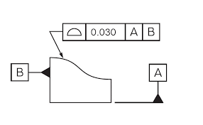
Once datums are defined, the profile symbol is placed on the drawing using a feature control frame. This frame contains the profile symbol, the tolerance value, and the applicable datums. For example, a surface profile tolerance might be specified as Ⓑ 0.2 | A | B | C, meaning that the surface must lie within 0.2mm of the ideal geometry relative to datums A, B, and C. Clear annotation ensures machinists and inspectors understand the design requirements without confusion. By following this systematic approach, engineers can create a GDT profile that is both precise and easy to interpret.
To achieve a flawless GDT profile, engineers must follow industry best practices that promote clarity and consistency. One of the most important practices is to keep tolerances realistic. Overly tight tolerances may drive up manufacturing costs unnecessarily, while excessively loose tolerances may compromise functionality. The goal is to strike a balance between manufacturability and performance. Consulting with manufacturing teams during the design phase can help establish practical tolerances that meet functional needs without burdening the production process.
Another best practice is to use CAD tools effectively. Modern CAD software has integrated GD&T modules that allow designers to apply and visualize profile tolerances directly on 3D models. These tools reduce errors, ensure compliance with ASME Y14.5 or ISO standards, and improve communication between design, manufacturing, and quality teams. Additionally, consistent documentation and adherence to established standards ensure that every stakeholder interprets the GDT profile uniformly, avoiding miscommunication and costly mistakes in later stages of production.
While the GDT profile is powerful, many designers fall into common pitfalls that compromise its effectiveness. One frequent mistake is misusing datums. Incorrect datum selection or failing to define datums altogether leads to tolerance zones that are impossible to interpret or measure. For example, applying a surface profile without a proper reference frame can result in inspectors interpreting the tolerance differently, leading to disputes between design and manufacturing teams. Always ensure datums are clearly defined and logically support the function of the feature.
Another common error is the misuse of profile tolerances on non-critical features. Over-applying profile tolerances to every surface may unnecessarily complicate the inspection process and increase costs. Instead, designers should apply profile tolerances only where necessary to ensure fit, function, or aesthetic requirements. Over-dimensioning not only burdens quality control but can also confuse machinists who may misprioritize features. By avoiding these mistakes, engineers can maximize the efficiency and clarity of their GDT profiles.
In modern manufacturing, where precision and efficiency are paramount, the GDT profile has become indispensable. Industries such as aerospace, automotive, and medical device manufacturing rely heavily on profile tolerances to achieve high-quality parts with minimal variation. For instance, turbine blades in jet engines or orthopedic implants in healthcare require surfaces to meet stringent profile tolerances to function safely and effectively. Without GD&T profile controls, ensuring such accuracy would be nearly impossible using traditional tolerancing methods.
Moreover, the role of digital technology in manufacturing has elevated the importance of GDT profiles. With the rise of Computer Numerical Control (CNC) machining and Coordinate Measuring Machines (CMMs), profile tolerances can be directly programmed and inspected digitally. This seamless integration between CAD, CAM, and inspection tools reduces human error, enhances productivity, and ensures compliance with international standards. As industries continue to evolve toward smart manufacturing and Industry 4.0, the GDT profile will remain a critical tool for maintaining quality and ensuring global compatibility in engineering practices.
Creating a perfect GDT profile for engineering drawings requires a deep understanding of GD&T principles, careful planning, and adherence to best practices. By grasping the fundamentals, following systematic steps, avoiding common mistakes, and leveraging modern digital tools, engineers can ensure that their drawings convey design intent with absolute clarity. A well-applied profile tolerance not only improves communication across design, manufacturing, and quality teams but also ensures that products meet their intended function, fit, and form.

Social Media Marketing Strategies for Beginners
Mar 14 2023
.jpeg)


(0) Comments